
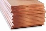
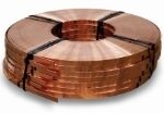
At Bronmetal we supply high quality copper flat bars in line with the most relevant international standards. We can supply copper flat bars in a roll or in lengths, adapting to your needs.

Flat copper bar / rectangular bar
Copper flat bars for electrical applications.
Supply formats:
-

Flat
-
Roll
-
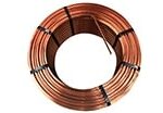
Reek
Medidas:
Thicknesses from 2 to 70 mm. ; widths from 10 to 250 mm.
Medidas:
Thicknesses from 2 to 70 mm. ; widths from 10 to 250 mm.
Medidas:
Thicknesses from 3 to 70 mm. ; widths from 10 to 250 mm.
Data sheet: Flat copper bar / rectangular bar
ALLOYS. COMPOSITION OF Cu-OFE and Cu-PHCE ACCORDING TO EN 13601
| Material Designation | Composition in % (m/m) | |||||||||
|---|---|---|---|---|---|---|---|---|---|---|
| Element | Cu | Ag | Bi | O | P | Pb | Other elements (see note) | |||
| Symbolic | Numerical | |||||||||
| Total | Excluded | |||||||||
| Cu-ETP | CW004A | min. | 99.90a | - | - | - | - | - | - | Ag, O |
| max. | - | - | 0.0005 | 0.040b | - | 0.005 | 0.03 | |||
| NOTE – The total of other elements (different from copper) is defined as the sum of Ag, As, Bi, Cd, Co, Cr, Fe, Mn, Ni, O, P, Pb, S, Sb, Se, Si, Sn, Te, and Zn, excluding any of the elements whose individual value is indicated. | ||||||||||
| a Including silver (Ag), up to a maximum of 0.015% | ||||||||||
| b Up to 0.060% of oxygen content is permitted, subject to an agreement between customer and supplier. | ||||||||||
| c Oxygen content must be such that the material fulfills the requirements for hydrogen embrittlement resistance as defined in EN 1976. | ||||||||||
ALLOYS. COMPOSITION OF Cu-OFE and Cu-PHCE ACCORDING TO EN 13601
| Material Designation | Element | Composition in % (mass fraction) | |||||||||||||||||
|---|---|---|---|---|---|---|---|---|---|---|---|---|---|---|---|---|---|---|---|
| Symbolic | Numerical | Cu | Ag | As | Bi | Cd | Fe | Mn | Ni | O | P | Pb | S | Sb | Se | Sn | Te | Zn | |
| Cu-OFE | CW009A | min. | 99.99 | - | - | - | - | - | - | - | - | - | - | - | - | - | - | - | |
| max. | - | 0.0025 | 0.0005 | 0.0002 | 0.0001 | 0.00010 | 0.0005 | 0.0001 | _a | 0.0003 | 0.0005 | 0.0015 | 0.0004 | 0.0002 | 0.0002 | 0.0001 | |||
| Cu-PHCE | CW022A | min. | 99.99 | - | - | - | - | - | - | - | - | 0.001 | - | - | - | - | - | - | |
| max. | - | 0.0025 | 0.0005 | 0.0002 | 0.0001 | 0.00010 | 0.0005 | 0.0001 | _a | 0.006 | 0.0005 | 0.0015 | 0.0004 | 0.0002 | 0.0002 | 0.0001 | |||
| a The oxygen content must be such that the material fulfills the requirements of hydrogen embrittlement resistance as specified in EN 1976. | |||||||||||||||||||
ELECTRICAL PROPERTIES (ONLY CONDUCTIVE ALLOYS)a
| TEMPER | Ø OR DISTANCE BETWEEN PARALLEL SURFACES | MAX. ELECTRICAL RESISTIVITY, ΩG/m2 AT 20ºC (68ºF) | ||||
|---|---|---|---|---|---|---|
| C10100 | C10200, C10400, C10500, C10700, C10920, C10930, C10940, C11000, C11300, C11400, C11500, C11600 | C10300 | C12000 | Rockwell Hardness Scale F, 60 kg load, 1/16 inch ball | ||
| O60 | ALL SIZES | 0.151 76 | 0.153 28 | 0.156 14 | 0.16661 | 50 max |
| H04 | Up to 3/8 in. (10 mm) incl. | 0.155 85 | 0.157 37 | 0.159 40 | 0.17031 | |
| Between 3/8 in. (10 mm) and 1 in. (25 mm) incl. | 0.155 85 | 0.157 37 | 0.159 40 | 0.17031 | 80 min | |
| Between 1 in. (25 mm) and 2 in. (50 mm) | 0.155 85 | 0.157 37 | 0.159 40 | 0.17031 | 75 min | |
| Between 2 in. (50 mm) and 3 in. (75 mm) | 0.154 25 | 0.155 77 | 0.159 40 | 0.17031 | 65 min | |
| Greater than 3 in. (75 mm) | 0.154 25 | 0.155 77 | 0.159 40 | 0.17031 | ||
| H02 | Up to 3/8 in. (10 mm) thickness and up to 4 in. (110 mm) width | 0.155 85 | 0.157 37 | 0.159 40 | 0.17031 | 80 min |
| Other dimensions | 0.154 25 | 0.155 77 | 0.159 40 | 0.17031 | 65 min | |
| Profiles | 0.154 25 | 0.155 77 | 0.159 40 | 0.17031 | ||
| a Flats, bars, and profiles made from UNS copper alloys C10100, C10200, C10300, C10400, C10500, C10700, C10920, C10930, C10940, C11000, C11300, C11400, C11500, C11600, and C12000 shall conform to the electrical resistivity limits specified in this table for the corresponding copper grade, temper, shape, and size, when tested in accordance with test method B193. | ||||||
| ASTM | EN | DIN | AFNOR | BS | JIS | SN | ||
|---|---|---|---|---|---|---|---|---|
| SYMBOLIC | NUMERIC | SYMBOLIC | NUMERIC | |||||
| C11000 | Cu-ETP | CW004A | E-Cu58 | 20065 | CuA1 | C101 | C1100 | Cu-ETP |
| C10100 | Cu-OFE | CW009A | – | – | CuC2 | C110 | – | Cu-OFE |
| C10200 | Cu-OF | CW008A | OF-Cu | 20040 | CuC1 | C103 | C1020 | Cu-OF |
| – | Cu-HCP | CW021A | Se-Cu | 20070 | – | – | – | – |
| C10300 | Cu-PHC | CW020A | Se-Cu | 20070 | – | – | – | Cu-HCP |
| – | Cu-PHCE | CW022A | – | – | – | – | – | – |
| C10700 | CuAg0.10 | CW013A | CuAg0.10 | 21203 | – | – | – | – |
| C10940 | ||||||||
| C11600 | ||||||||
| C11904 | CuAg0.04P | CW014A | – | – | – | – | – | – |
| C11907 | CuAg0.10P | CW016A | CuAg0.1P | 21197 | – | – | – | CuAg0.1P |
| C12200 | Cu-DHP | CW024A | – | – | – | – | – | – |
MECHANICAL PROPERTIES (ALL ALLOYS)
| TEMPER | Ø OR DISTANCE BETWEEN PARALLEL SURFACES | TENSILE STRENGTH, ksi (MPa) a | YIELD STRENGTH, ksi (MPa) Min. b | ELONGATION IN 4 X DIAMETER OR THICKNESS OF SAMPLE MIN % c | BEND TEST ANGLE | |
|---|---|---|---|---|---|---|
| MIN | MAX | MIN | ||||
| O60 | ALL SIZES | 28 (195) | 37 (255) | 8 (55) b | 25 | 180 |
| H04 | Up to 3/8 in. (10 mm) incl. | 45 (310) | 60 (410) | 12 | 120 | |
| Between 3/8 in. (10 mm) and 1 in. (25 mm) incl. | 40 (275) | 55 (380) | 12 | 120 | ||
| Between 1 in. (25 mm) and 2 in. (50 mm) | 35 (240) | 50 (345) | 15 | 120 | ||
| Between 2 in. (50 mm) and 3 in. (75 mm) | 33 (230) | 48 (330) | 15 | 120 | ||
| Greater than 3 in. (75 mm) | 30 (205) | 48 (330) | 15 | 120 | ||
| H02 | Up to 3/8 in. (10 mm) thick and up to 4 in. (110 mm) wide | 37.5 (260) | 50 (345) | 10 | 120 | |
| Other sizes | 33 (230) | 50 (345) | 15 | 120 | ||
| Profiles | Not specified d | d | 15 | |||
| a ksi = 1000 psi | ||||||
| b Slight straightening is permitted | ||||||
| c In any case, a minimum gauge length of 1 inch shall be used | ||||||
| d Subject to special agreement between manufacturer or supplier and purchaser | ||||||
| STANDARD | FORMERLY |
|---|---|
| O60 | Soft Annealed |
| H02 | Half Hard |
| H04 | Hard |
THICKNESS TOLERANCES
| THICKNESS | Width in inches (width in mm) | |||
|---|---|---|---|---|
| Up to 2 (50) incl. | Between 2 (50) and 4 (100) incl. | Between 4 (100) and 8 (200) incl. | Between 8 (200) and 12 (300) incl. | |
| Up to 0.500 (13) incl. | 0.003 (0.08) | 0.004 (0.10) | 0.0045 (0.11) | 0.0055 (0.14) |
| Between 0.500 (13) and 1.000 (25) incl. | 0.004 (0.10) | 0.0045 (0.11) | 0.005 (0.13) | 0.006 (0.15) |
| Between 1.000 (25) and 2.000 (50) incl. | 0.0045 (0.11) | 0.005 (0.13) | 0.006 (0.15) | |
| NOTE: When the specified tolerance value is all positive or all negative, the values shown must be doubled. | ||||
Documentation download
Title
Other languages
Type
Created
You may also like